


INTRODUCTION
Dental medicine has usually engaged in traditional non-digital occlusal indicators to assess the force levels of occlusal contacts.1 Articulating paper is the most common conventional mode of occlusion detection which determines the contacts of teeth based on the ink marks of varying sizes and colour intensities on the teeth.2,3 Subjective interpretation principles are still the most common type of method taught as being the most apt for patients, despite the fact that studies show dentists choose incorrectly both forceful and non-forceful contacts when using its principles of size predicting load.1–4
Despite the lack of scientific evidence, subjective interpretation has been a long- standing, well-accepted method by which clinicians supposedly can determine the relative occlusal force content of occlusal contacts.1–4 It has been advocated that mark size is representative of the load contained within the mark.2,5 Traditional static dental occlusal registration materials like foil, articulating paper/ribbon, ink impregnated strips, wax, or silicone imprints do not quantify occlusal forces, detect occlusal contact time-sequencing, or detect force transmission around the dental arch.6,7
Studies on articulation paper have only analysed physical properties of the marking strips like thickness, composition, ink substrate and plastic deformation and has never detailed about articulating paper being able to measure relative occlusal force.8 Carey et al. Indicated that relative mark size could not be used reliably to measure the relative occlusal force.8 Multiple studies have revealed a lack of correlation between the size of articulating paper markings and applied occlusal load.9,10 The authors reported a high variability of mark sizes was associated with each test load, showing that numerous mark sizes were representative of a single load.8 Articulating paper is non-repetitive from use to use because its matrix is destroyed as ink is lost when articulating paper is repeatedly occluded into, and it cannot sequence contact timing order or duration.5,11 This study showed articulating paper demonstrates a high degree of false positive markings and that the reproducibility of these systems is poor, resulting in significant variations in the size and number of markings.12 Hence clinicians are required to use their skill and experience to subjectively interpret the marks and distinguish false positives from true occlusal contact. However, even with experience articulating papers only indicate occlusal contact location but not the occlusal force levels or contact timing durations.
To counter these problems, computerized occlusal analysis technology was first introduced in the mid-1980s.8 The T-Scan (Tekscan, Inc. South Boston, MA USA) quantifies and displays relative occlusal force information, so the clinician can minimize the errors of incorrect occlusal contact selection that occur from relying solely on the combination of dental articulating paper and patient feel.2 T-Scan III can help ensure that high quality and complete occlusal end results are predictably obtained from clinical occlusal treatment.
The specific aims of this study were to test the clinical competence of prosthodontists using subjective interpretation of articulating paper markings when identifying the point of highest interference point and to determine whether subjective interpretation of articulating paper markings is a reliable method for clinicians to employ when determining occlusal contact relative force content.
MATERIALS & METHODS
Fifty prosthodontists were randomly chosen for the study. Out of them only thirty-two of them took part actively in the study. Thirty-two prosthodontists were part of the study with varying years of clinical experience ranging from 5-10 years. The inclusion criteria were that the participant is a practising prosthodontist with a sound knowledge on occlusion and occlusal adjustment/correction of natural teeth or prosthesis. All the participants were informed about the study and only those who consented were made part of the study.
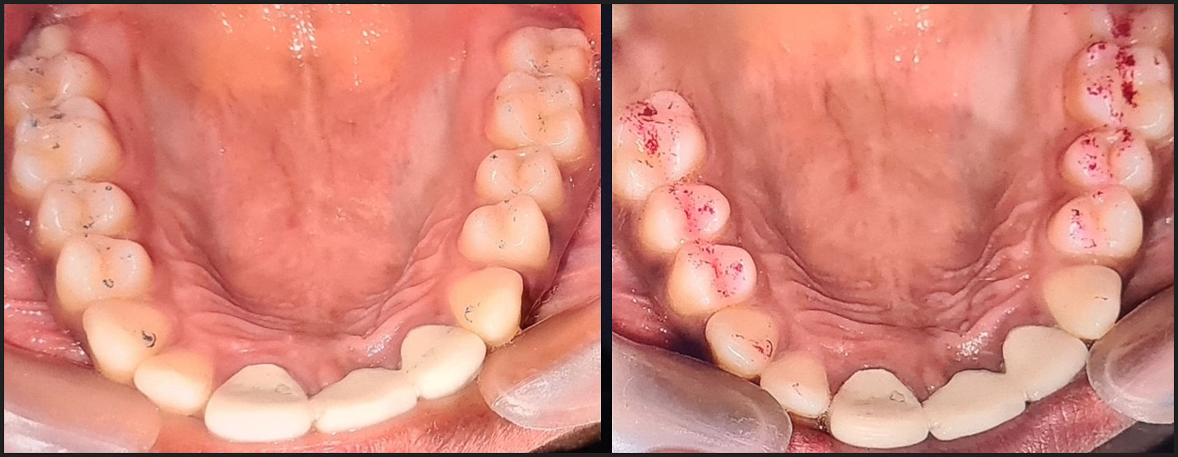
A single maxillary and mandibular occlusal view photograph were shot with indirect view using a mirror after being fully marked with articulating paper. A photograph was taken for both the 40-micron and the 100-micron thickness of articulating paper. None of the points were marked to authenticate further the double-blind study.
The dentist/participants were asked to identify the most forceful contacts in each photograph of both 40-micron and 100-micron thickness. The dentist was asked to mark the contact based on subject interpretation skills that they have gained over years of clinical practice.
The patient was also recorded with T-Scan to determine the real occlusal interferences. The results were compared to the results obtained from each participant. The participants were unaware of the T-Scan results from the patient. The discrepancies observed both with 40-micron thickness and 100-micron thickness were recorded from each participant. They were represented with graphs to reveal of the amount of discrepancy from each participant.
RESULTS
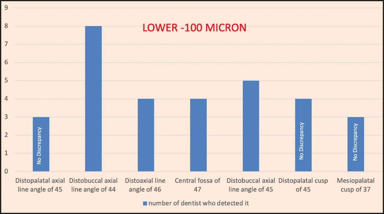
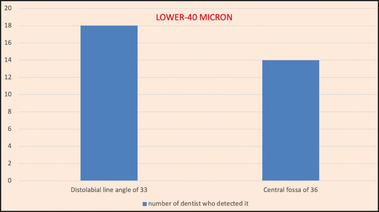
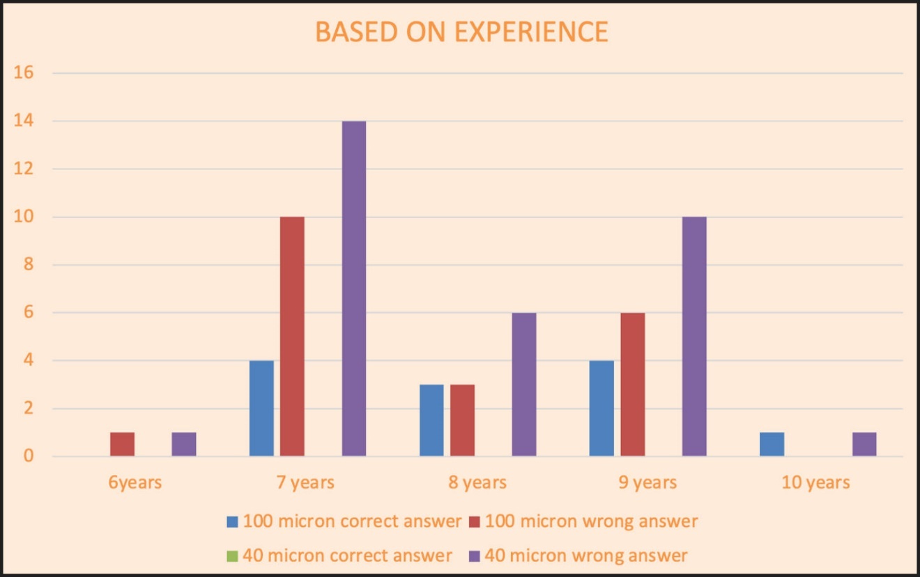
The most common first choice markings for 100 micron articulating paper in the upper arch was mesiobuccal cusp of 16 and for the lower arch is distobuccal axial line angle of 44 (Table 1). While using the 40-micron articulating paper, the most common choice was Mesiopalatal axial line angle of 23 in the upper arch and Distolabial line angle of 33 in the lower arch. Only four participants chose any correct answers with the 100-micron thickness articulating paper and no correct answers with 40-micron thickness (Table 2). The results also showed that higher experience did not help in deciphering the high points accurately with the articulating paper.
Table 1 gives the detailed results of the study. The table shows the actual high points in the patient and the high point identified by the dentist/participants during the study. The tabular column also shows the discrepancy both in 100-micron and 40-micron papers along with their years of experience. The results are represented in a bar graph.
DISCUSSION
The findings of this study strongly indicate that dentists cannot accurately determine high occlusal force contacts by making subjective interpretation. Visual assessments of articulating paper mark size, colour-depth, and shape cannot be used as a tool for determining the point of high force or interference in occlusion. The result of this study supports the findings of the previously published subjective interpretation studies.1–4
In this study, all participants observed 2 occlusal view clinical photographs, one with marks from 40-micron thickness of articulating paper and one with marks from 100-micron thickness articulating paper.
The table and the pictorial representation of the results with the use of a bar graph shows very clearly that the number of times the dentist chose the right point was very low or negligible. This was true in the case of the 100-micron (Graphs 1 & 2) articulator paper marking. It was particularly a surprise to note that a larger number of discrepancies were seen with 40-micron thickness marking. This was clearly against the conventional thought that thinner articulating papers will help dentist depict the occlusal interference more accurately during subjective interpretation than with a thicker articulating paper.1,2


Most importantly, the very limited ability of the dentist-participants to choose the correct high force contacts, was in excellent agreement with the findings of both prior subjective interpretation studies.2,3
The fact that only 4 participants with correct answers with 100-micron thickness articulating paper and no correct answers with 40-micron thickness possibly shows that the correct answers could have occurred purely by chance and not by experience or knowledge. Whatever rules the participants used to select the high force contacts, their rules led them to mostly wrong answers.1
The most common first choice markings for 100 micron articulating paper in the upper arch is mesiobuccal cusp of 16 and for the lower arch is distobuccal axial line angle of 44. Similarly, while using the 40-micron articulating paper, the most common choice was mesiopalatal axial line angle of 23 in the upper arch and distolabial line angle of 33 in the lower arch. Graphs 3 & 4.


In both cases the darkest and largest markings in the photograph was chosen by the participants, suggesting that these were favoured selections because of the size of the marks and their dark colour and their prominence, which falsely indicated a “forceful” contact.1 They might have also been chosen because of where they were located on the teeth, such as being on an incline.1,2 This indicates that the participants were not able to truly discriminate different force levels when looking at the thickness or darkness of the paper makings. See Figures 1 and 2.
_and_100-micron_(pink)_articulator_marki.jpg)
_and_100-micron_(pink)_articulator_mark.jpg)
Smaller marks are often areas of stress concentration and larger marks are areas of stress distribution and it has been established that as occlusal forces go up, mark sizes go down. This has been revealed by Carey, et al, and Saad, et al.3,8 Hence, although the large dark marks look forceful, they have led the participants astray from finding the correct high force contacts.5 The other reason for wrong detection of high points was that the picture of the ink markings was being observed without any patient’s response or input to help the clinician ascertain any areas of perceived contact “highness.” Hence, these studies prove and support our study results that subjective interpretation is not a reliable method to determine the occlusal high-force points and occlusal interferences.
This study also supports that even having more experience in the field of prosthodontics did not help in subjectively detecting the high-force points accurately. Thus, revealing that even after years of experience, specialty knowledge, and higher technical skills, it was not possible to consistently detect the high-force points accurately only with subjective interpretation. Their very limited success, (17.5 %) with 100-micron paper, (0 %) with 40-micron paper, even though slightly improved over previous studies, (5 – 13 %) for references 1, 2 & 3, suggests that subjective interpretation is just not adequate. See Graph 5. However, it is unknown to what extent random chance played a part in these outcomes.

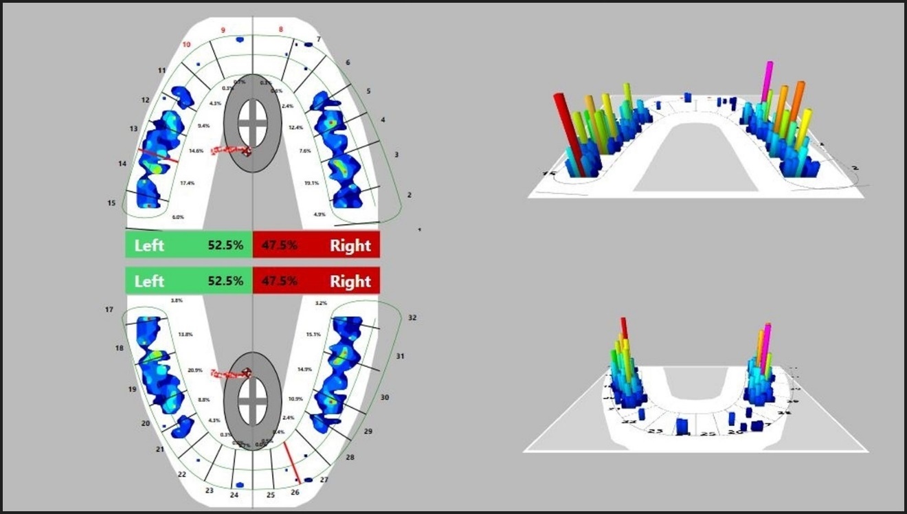
The T-Scan method on the contrary is an objective method to determine the occlusal interference and high-force points. It can readily determine the most forceful contacts with accuracy, which the participants struggled to locate with the articulating paper. See Figure 3. The T-Scan system removes the subjectivity of looking at paper markings and replaces it with objective force and timing data sets that guide a clinician to make targeted and accurate occlusal corrections of the truly forceful contacts.1 Thus, T-Scan usage can help accurately correct the occlusion without inadvertent aberrant occlusal grinding that can lead to tooth structure fracture, occlusal wear, tooth mobility, abfraction formation, gingival recession, periodontal bone loss, and peri-implant bone loss.1

LIMITATIONS
Only two occlusal indicator papers were used and there are many others that might have functioned somewhat differently. As mentioned, the prosthodontists did not see the actual patient or receive any feedback that might have been helpful in the interpretation of paper marks. However, these results were in good agreement with previous studies.1–4,8,10
CONCLUSION
Articulating papers provide ink markings which can be interpreted only subjectively by the dentist using their skill, specialty knowledge, and experience. The interpretation is solely based on the discretion of the dentist. Hence, subjective interpretation is an arbitrary and inaccurate way of detecting high-force points and occlusal interference in a patient. This leads clinicians to make improper contact selections by usually selecting large dark marks as high-force points. Hence, resulting in an excessively invasive treatment approach when performing occlusal adjustments.
Replacing this subjective interpretation method with objective measurements is the need of the hour, where the accurate location, amount of force and the time duration at each point are measured with accuracy. It will help the dentist to accurately locate and correct real interferences without any occlusal risk and thus in the best interest of the patient.
Statement of Conflict
No conflict of interest was reported.
Statement of Funding
No funding was provided from any source for this project.